Issue
Some of the work I do, such as soldering components with large thermal mass on multi-layer boards, requires the use of a high-powered, temperature controlled soldering station with fast thermal recovery and lead-free soldering capability. An under-powered 35W soldering station I already own, just isn’t suitable for that type of work. So, I treated myself with a PACE ST-50 80W Digital Soldering Station which came with a composite / cartridge type soldering iron and a standard tool stand. Since the heater element and thermal sensor have been integrated into the soldering iron tip, the thermal transfer is excellent and overshoot is eliminated. The build quality of this station is exceptional.
PACE also offers a smart tool stand that is capable of detecting the presence of the soldering iron. It is called an ISB or Instant-SetBack Cubby (Part #: 6019-0084-P1) and it costs around 100 USD. When the ISB Cubby detects the presence of the TD-100 soldering iron, it waits for 45 seconds and then puts the iron into the temperature Setback mode. Setback Mode means that the temperature is reduced to just below solder melt temperature (176°C/350°F) so the corrosive action of the leaded or Lead-Free solder is stopped, maximizing the life of the tip and minimizing the electricity bill. When the iron is removed from the cubby, the system returns to normal operation within seconds. The mentioned cubby is suitable for ST 30, ST 50, ST 65, ST 70, ST 75, ST 115, WJS 100, MBT 301 & MBT 350 units.
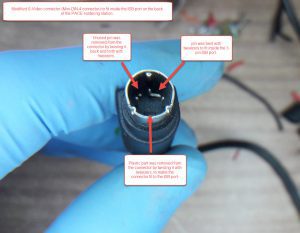
Since ISB Cubby Mini-DIN-3 port has been present on the back side of my unit, I did some research on the soldering iron detection mechanism. I came up with a simple, but reliable do-it-yourself, minimal component and low cost solution. All the information required was provided in this thread on the eevblog.com. I was reluctant to use a simple mechanical switch due to the reliability issues; the iron handle is too light to surely activate the switch every time, moreover switch shorting or burn could occur in the harsh, high-temperature and solder spatter contaminated environment. I couldn’t use an infrared activated switch solution since I didn’t have an IR photo-transistor or an IR LED on hand. However, I could easily find an ordinary white LED diode, a photoresistor (or light-dependent resistor, LDR, or photocell; light-controlled variable resistor), NPN transistor (or bipolar junction transistor, BJT for short), 500K potentiometer (or pot, variable resistor, rheostat) and a Mini-DIN-3 connector cable (a modified Mini-DIN-4, Mini-DIN-7 or S Video Cable can also be used). These are all the parts that are needed for this simple light-activated switch / soldering iron detection circuit.
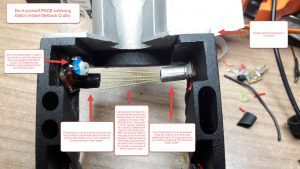
Tools and parts required:
- A Soldering iron
- Flat tweezers
- An ALU tape (Common household ALU foil or other light reflective element can be used instead)
- A Black silicon tubing (electrical insulating tape can be used instead)
- A white LED diode (SMD or through-hole type can be used, the brighter the better)
- A SMD or through-hole resistor used for regulating current of the LED diode (value depends on the forward voltage and maximum current of the LED diode used, usually 100 – 470 ohms)
- A photoresistor (also known as: light-dependent resistor, LDR, photocell or a light-controlled variable resistor)
- A 500K or similar value variable resistor (or a potentiometer, pot, rheostat, code on the 500K is usually 504)
- NPN Silicon Transistor (or bipolar junction transistor, BJT for short, small signal S8050 is used in the circuit described)
- Mini-DIN-3 connector cable (modified Mini-DIN-4, Mini-DIN-7 or S Video Cable connector can also be used)
- Superglue or epoxy for mounting the components (hot glue is not recommended since it could melt at higher temperatures)
- Optional components: 1N4007 diode for reverse polarity protection and PolySwitch re-settable fuse (PPTC for short, ideally rated at 100mA) or similar for short-circuit protection.
Procedure
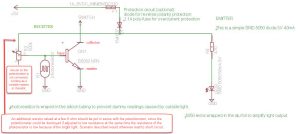
I will not go into the details on how to build this very basic circuit. I’ll rather describe its working principle and accompany it with a schematic. The circuit is essentially made from two parts – the emitter and receiver. The emitter is just an ordinary white LED diode connected to the +5V line. On the other end there is a receiver – a simple photoresistor in a voltage-divider circuit together with the variable resistor, controlling or driving the NPN transistor.
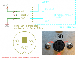
ISB Mini-DIN 3 port
If you have one of these units: ST 30, ST 50, ST 65, ST 70, ST 75, ST 115, WJS 100, MBT 301 or MBT 350, there is a mini-DIN-3 connector port on the back of the soldering station. +5V line will be used to supply power to your DIY ISB circuit. The SWITCH line is used for communication with the micro-controller inside the PACE station, about the presence of the soldering iron in the ISB Cubby. When there is no soldering iron present or the ISB Cubby is not connected to the station, the line is pulled HIGH (to +5V), via the pull-up resistor inside the station. If you measure the voltage on the mentioned line, it should read a bit below +5V. When the soldering iron is placed into the ISB cubby, SWITCH line is pulled LOW (to GND) by the ISB Cubby’s circuitry and the micro-controller initiates the 45 second countdown, before lowering the temperature of the soldering iron to 176°C/350°F. This behaviour can be simulated by shorting the GND and SWITCH lines on the ISB port with a piece of wire.
EMITTER – an ordinary white LED
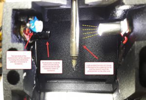
The LED diode can be wrapped in an ALU tape / ALU foil or similar light reflective material to amplify and concentrate its light output to the photoresistor on the receiving end of the circuit. The current limiting resistor must be used in series with the LED diode. Its value can be calculated based on the properties of the LED used. An online calculator can be used.
RECEIVER – a photoresistor circuit
Photoresistor and potentiometer are used in a simple voltage-divider circuit, regulating the voltage on the base of the NPN transistor. When photoresistor is receiving the light emitted from the LED (no soldering iron is in the ISB cubby, blocking the light), its resistance is low, thus pulling the voltage on the base of the NPN transistor LOW. In this case the connection between the collector and emitter pins of the NPN transistor is open, the SWITCH line stays HIGH; microcontroller inside the soldering station “knows” there is no soldering iron present in the ISB cubby. When the soldering iron is placed into the ISB cubby, the light from the LED diode to the photoresistor is blocked. In this case the resistance of the photoresistor is high and so is the voltage on the base of the NPN transistor. NPN starts conducting (connection between the collector and emitter pins is established), the SWITCH line is pulled LOW (to GND). Microcontroller is now “aware” the soldering iron is being placed in the ISB cubby. It initiates a 45 second countdown, before lowering the temperature of the soldering iron to 176°C/350°F. When the soldering iron is removed from the ISB cubby, its temperature instantly starts to increase to the user set value and is ready to be used within seconds. The sensitivity of the circuit can be adjusted by slowly turning the potentiometer and thus increasing or decreasing its resistance. To increase the reliability of the circuit, photoresistor needs to be protected from an uncontrolled outside light by a black silicone tubing. WARNING: If there is no resistor (a few K ohm) in series with the potentiometer on the +5V line, and the potentiometer is adjusted to low resistance, at the same time the photoresistor is low resistance (it is under direct light), the +5V and GND lines would be shorted. This would result in a damaged potentiometer.
SAFETY FIRST
I hope it goes without saying, the circuit should be extensively tested on a LAB bench power supply, before connecting it to the actual PACE soldering station. Otherwise, damage to the micro-controller could occur, rendering the soldering station unusable.
At this time, the sensitivity of the circuit should be carefully adjusted by connecting the multimeter (in resistance measurement mode) to GND and SWITCH lines and setting the potentiometer, based on the values displayed by the multimeter. It should display O.L. or OPEN when there is no soldering iron placed in the ISB cubby. When soldering iron is present in the ISB cubby (blocking the light from the LED diode to the photoresistor), resistance between the GND and SWITCH lines should be low (in my case around 40 ohms). If any component in the circuit is heating extensively, something is wrong and should be thoroughly investigated before connecting the ISB cubby to the soldering station.
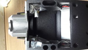
After the circuit has been working reliably for a few days, being connected to the PACE soldering station, it is time to consider protecting it from the hostile environment it is operating in; especially from the solder spatter which could cause shorts and potentially damage the circuit along with the micro-controller. The circuit could be encased in a temperature resistant plastic or in my case, covered by protective sheets (with the circular openings for the photoresistor and LED tubing), made from a layer of Kapton tape (non-conductive, temperature resistant) with a layer of ALU foil on top of it. The protective sheets can be removed, if the need to alter the circuit arises in the future.
Word of caution
Electronics repair is not difficult, but it requires a lot of patience, calmness, focus, a steady hand and some common sense. When in doubt or when you do not fully understand something, educate yourself first by checking it online, before following the step in question. If you do not feel competent enough to follow a given procedure, it is best to seek help from an expert technician in your area. I cannot be held responsible for any damage caused to yourself, your equipment or to the device you are repairing as a result of following this tutorial.
If you have found this blog post useful and would like to buy me a cup of coffee, please click here :)
hi!
thanks for sharing this info, indeed very usefull.
regards,
You are welcome.
Thank you I,m going to try to use this plan with IR I really want this. THANK YOU again
You are welcome and thank you for your comment.
I would like to say that this has been working for me flawlessly for the past 2 years and a half.
If you require any additional help you can contact me at info@getgui.com
If you don’t want to build your own detector, here’s an inexpensive ready-made solution:
https://www.amazon.com/gp/product/B07FJLMLVZ/ref=ppx_yo_dt_b_asin_title_o06_s03?ie=UTF8&psc=1
I mounted it on one side of the cubby using double-sided hook-and-loop tape so the PCB can be removed and replaced/repaired if necessary, and ran the wires through the holes in the rear of the cubby to the connector that plugs into the ISB port on the Pace power unit (in my case, an ST-115). I bent the LED and detector 90-degrees to point at the heater barrel on my SX-100 handpiece. The distance between the LED/detector and barrel is about 3/8″. The LED/detector don’t get hot being that close to the hot barrel. They stay at roughly room temperature, probably because heat rises straight up from the barrel.
The PCB has a tiny red LED power-on light and a light that goes on when there’s something in proximity to the infrared LED/detector pair. It also has a trimmer pot to adjust the sensitivity/distance, but I found that it was already adjusted perfectly for the distance to the heater barrel.
The output signal is +5VDC when not activated (iron removed) and GND when activated (iron in the cubby). This means you can directly connect the three pins on the PCB to the ISB jack on the back of the Pace power unit: +5VDC to +5VDC, GND to GND and OUT to SW.
Hardest thing to find was the 3-pin miniDIN plug. Got it here:
https://vetco.net/products/3-pin-mini-din-male-inline-plug-connector
It hasn’t arrived yet, so I’m not 100% sure it’ll fit, but it looks like it will. Meanwhile, I tested the circuit using jumpers with pins, etc.
At $2 apiece, the pre-made board made it really cheap and easy to get instant set back.