Issue
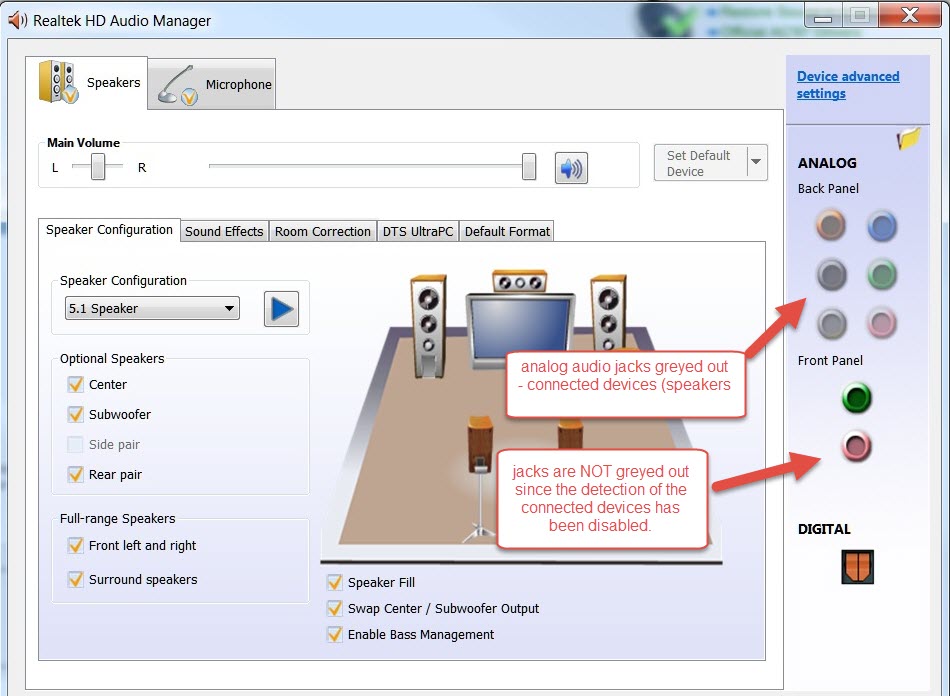
A friend of mine brought me this mini PC, based on a ZOTAC GeForce 9300-ITX WiFi motherboard. After freshly installing Windows 7 and all the required drivers from the motherboard manufacturer’s website, I connected speakers and noticed there is no sound output from any of the analog audio jacks. This PC features three jacks on the back and two on the front panel. After opening the Realtek HD Audio Manager, I noticed that analog jacks are all grayed out, which means the Realtek doesn’t detect when a device (speaker or headphone) is plugged in. I tried disabling front panel jack detection in HD Audio Manager and thus force the sound output from front panel jacks, even when device is not detected, no dice.
After trying a few more drivers; the latest driver directly from Realtek and a native Microsoft High Definition Audio Device driver, I concluded this is a hardware problem. I tried measuring audio jacks with a multimeter; no short circuits and no open connections relative to the motherboard. The fault lies in an on-board Realtek ALC662 IC chip or its circuit. I could try replacing the ALC662 IC, but since I don’t have one in stock, I opted for a second best option – replacing or bypassing the on board audio chip with an external USB sound card or DAC. Since an external USB sound card sticking out of the USB port would impact the portability of this mini PC to some extent, I decided to tear it apart and connect it directly to the unused USB header on the motherboard.
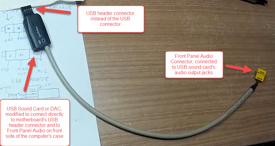
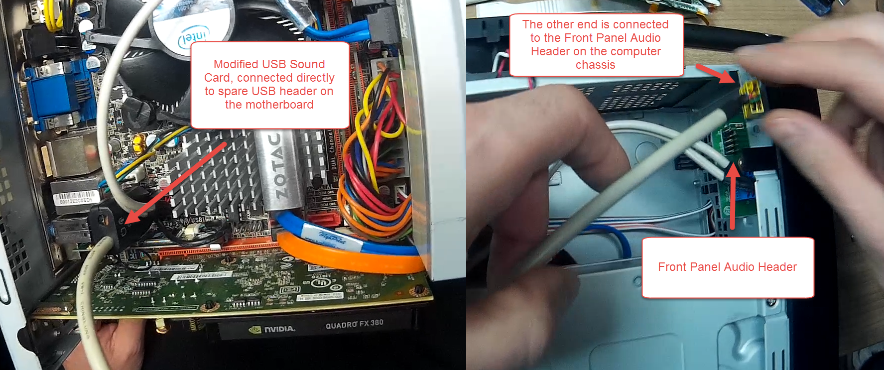
Below is a picture of the finished product – an external USB sound card or DAC, modified to fit inside of the computer case and connect directly to spare USB header on the motherboard.
Tools and parts required:
- External USB Sound Card (can be obtained from eBay or local computer parts store)
- Phillips screwdriver size #1
- Soldering iron with conical and chisel tips
- Sharp ESD safe tweezers
- 9 pin female USB header connector with cable (Not essential)
- 9 pin female Front Panel Audio header connector with cable (Not essential)
- If you don’t have the above two connectors on hand, you can use a few pieces of thin wire instead, and solder them directly to motherboard’s USB Header and Front Panel Audio Header on the computer chassis
- Some soldering skills
Procedure
The idea is to take apart the mentioned external USB sound card and connect it directly to an unused USB header on the motherboard. This way you don’t loose any of the free USB ports on your computer and the card is safely hidden inside of the computer case. The front panel audio jacks on the computer chassis are then connected to the USB sound card’s output audio jacks, to retain their intended purpose.
Locating an unused USB header connector
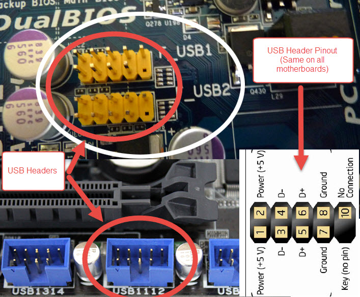
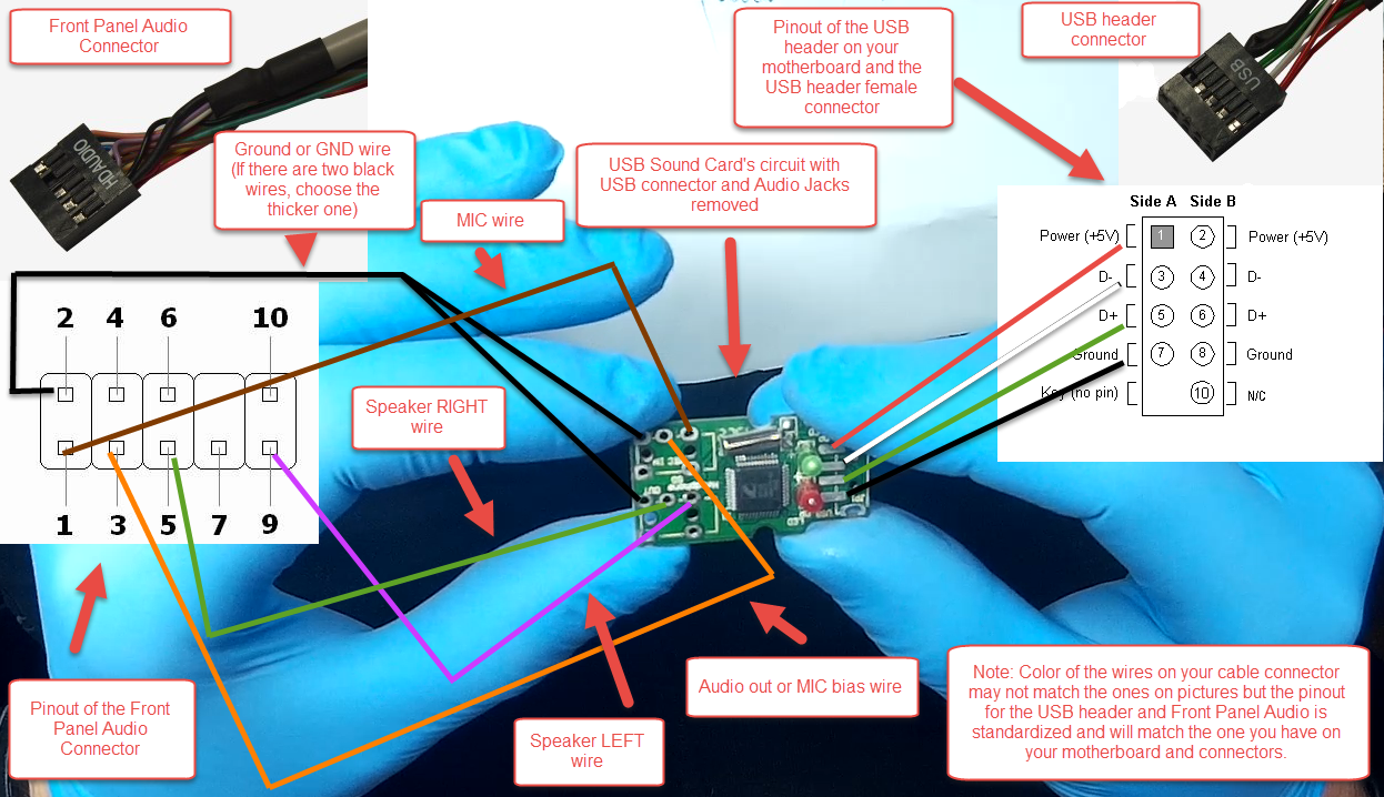
The first order of business is to locate an unused USB header connector on the motherboard, it usually has 9 pins sticking out of it, and in the near vicinity the text “USB” is written. Motherboard’s instruction manual can be of great help in this step. Use the picture below as a guide to visually locate it. One USB header can be used to connect two different USB devices since it has two rows of identical pins. On each row, from left to right, pins are: PIN1 = VCC or +5V, PIN2 = Data – or D-, PIN3 = Data + or D+, PIN4 = Ground or GND. The upper row has one additional pin, the fifth one, that is not used. This fifth pin exists just for orientation purpose.
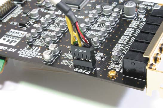
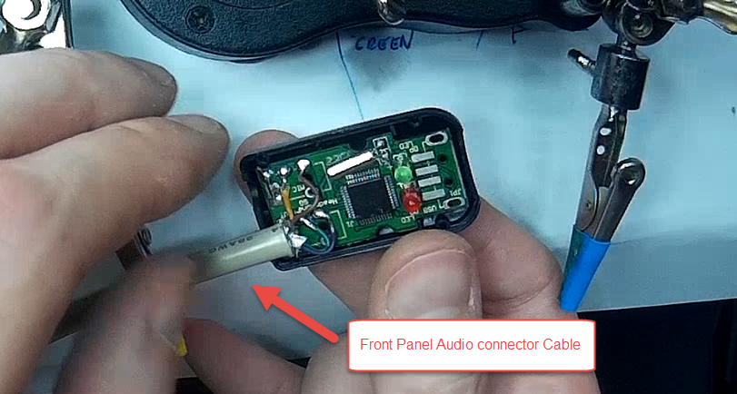
Locating Front Panel Audio connector cable
Now we need to locate the Front Panel Audio connector cable. The Front Panel Audio header looks similar to the mentioned USB header, but will have a Front Panel audio connector with cable connected to it and a text “FP_audio” or something similar written in the near vicinity. We will later connect it to the USB Sound card’s audio jacks. You can easily locate it by following the wires from the front side of the computer chassis (where front panel audio jacks are) to the FP audio header on the motherboard, it should be near the sound chip and back panel audio jacks. Instruction manual for the motherboard can also be of great help here.
External USB sound card DAC dis-assembly
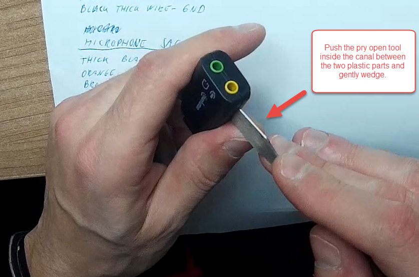
Push the plastic or steel pry open tool or a similar tool inside of the canal between the two plastic parts and gently wedge to release the plastic locks, holding the two pieces together. Try not to damage the plastic casing too much, as you will need it later in the process when you re-assemble the USB Sound Card.
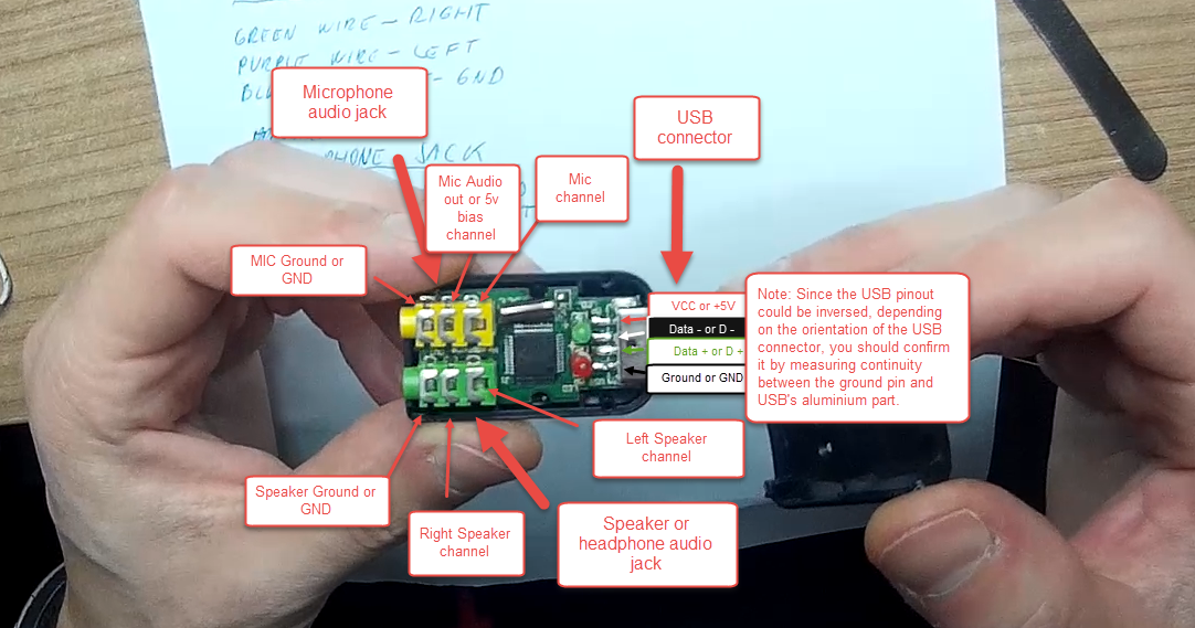
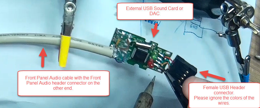
Confirming the pinout on the USB sound card DAC
Write down the pinout of your USB sound card and compare it to the photo above, before removing Audio jacks and USB connector from it. Removing jacks and the USB connector is optional, you could, of course, solder directly to the existing jack’s and USB connector’s pads or planes. Compare the USB Sound card’s pinout to the pinout of the USB Header connector and the Front Panel Audio connector. Use the picture below as a guide, before soldering the wires. If you don’t have a spare Front Panel Audio Header connector and USB Header connector at hand, you can instead solder the suitable thin and colored wires directly to the USB Header on the motherboard and to the Front Panel Audio Header on the computer chassis.
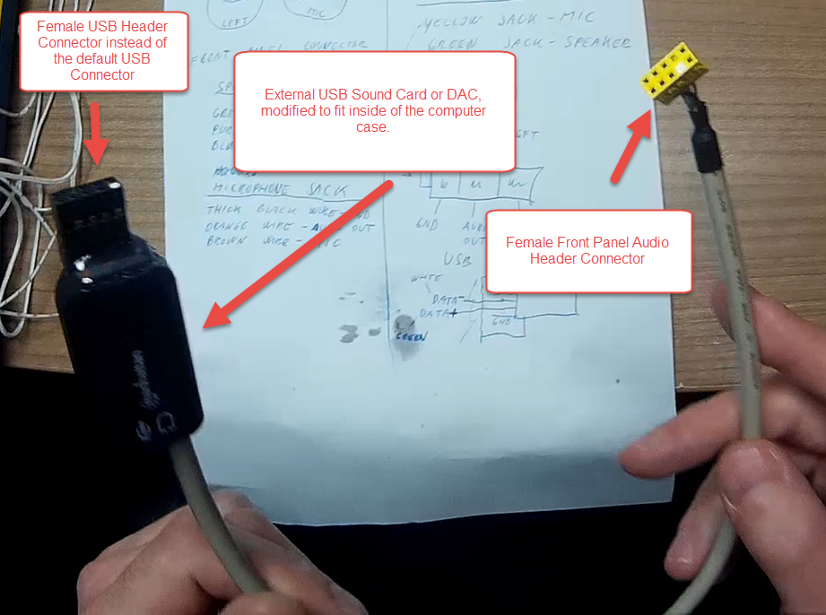
Below is a photo of the finished product, when re-assembled. New connectors are fixed to the plastic casing of the USB Sound Card with hot glue, to make the whole thing more resistant.
When the computer is started for the first time after the modified USB Sound Card – DAC is connected, it should automatically install the required drivers if the card is connected correctly. USB Sound Cards are usually Plug&Play, hassle free, type. You will probably just need to manually set it as a “Default device” via Control Panel -> Sound -> Playback. I imagine you could now do this blindfolded, since you probably spent at least few hours, tweaking sound settings and installing different drivers, before you realized this is a hardware problem.
The sound quality of this USB Sound Card is quite good, the only downside is, it only supports 2.1 channel configuration, compared to the original 6.1. But for the price of it, one couldn’t argue, since you can buy one from eBay for around 2 USD and for a few bucks more, from the local computer parts store. Avoid the ones with “virtual” 6.1 channel capabilities, as those additional channels truly are virtual.
Word of caution
Electronics repair is not difficult, but it requires a lot of patience, calmness, focus, a steady hand and some common sense. When in doubt or when you do not fully understand something, educate yourself first by googling, before following the step in question. If you do not feel competent enough to follow a given procedure, it is best to seek help from an expert technician in your area. I cannot be held responsible for any damage caused to yourself, your equipment or to the device you are repairing as a result of following this tutorial.
If you have found this blog post useful and would like to buy me a cup of coffee, please click here :)
Hi do u sell these? I can’t seem to find anything like this and this is what I’ve been looking for. I need the pci slot for a larger gpu. Thanks!